Vimag Labs’ Magnet-Free Motor Patent: Distinguishing Hype from Industry Reality
By Naresh Kumar Y · July 16, 2026

This article will examine the recent buzz surrounding Vimag Labs newly granted Indian patent for its "Virtual Magnet Synchronous Motor" (VMSM) to separate viral public relations excitement from the realities of electric vehicle engineering and patent law. While social media celebrates the design as a revolutionary, localized breakthrough to bypass rare-earth mineral dependencies, the piece details how the underlying technology relies on a classic, long-established engineering concept already used by major automotive giants. Rather than criticizing the grant, the text provides an approachable analysis of how patent criteria actually work, the real-world manufacturing trade-offs involved in software-driven motors, and what it truly takes to scale laboratory innovation into mass-market road vehicle production.
Recent viral posts have placed Bengaluru-based start-up Vimag Labs at the centre of widespread online attention. The start-up secured an Indian patent for their "Virtual Magnet Synchronous Motor" (VMSM), and the internet is buzzing.
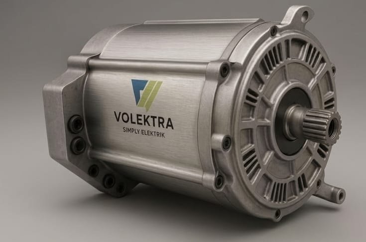 Indian Patent No. 590023, titled “A Robust Rotating Transformer Excited Synchronous Motor (RTESM) and Its Control,” was granted on 22 May 2026. It arose from Indian Patent Application No. 202211054118, filed on 21 September 2022 by Phyntelligence India Private Limited and published on 22 September 2023 in Patent Office Journal No. 38/2023, naming Luis Pont Lezica and Manish Seth as the inventors. Phyntelligence India Private Limited was subsequently renamed Volektra India Private Limited, with the company continuing under the same Corporate Identification Number, U73100DL2020FTC374715; the two names therefore refer to the same corporate entity rather than separate companies. Thereafter, under an Asset Purchase Agreement executed on 28 November 2025, Volektra India Private Limited, as the seller, agreed to assign and transfer its rights, title and interest in the listed intellectual-property assets to Vimag Labs Private Limited, as the purchaser. Schedule I of the agreement expressly identifies Indian Patent Application No. 202211054118 among the transferred patent assets, thereby contractually transferring the rights associated with the application to Vimag Labs before the patent was granted.
The patent describes a magnet-less and brush-less synchronous machine in which a rotating transformer and a three-phase rectifier electrically excite the rotor field without using permanent magnets. It runs an electric motor without any rare earth magnet inside it. Almost every EV today uses a Permanent Magnet Synchronous Motor.
It is always fantastic to see local hardware innovation taking off. But for someone who works in patent prosecution, it is worth taking a step back. Let's separate the exciting PR headlines from how patent law and real-world EV engineering actually work. Here is a breakdown of what this patent actually is, how the technology works, and the real-world engineering hurdles ahead
Here is a breakdown of what this patent actually is, how the technology works, and the real-world engineering hurdles ahead.
1. What is a "Magnet-Free" Motor?
To understand why people are excited, we have to look at how most EVs work today. Right now, almost all electric cars use permanent magnet motors. These rely on physical magnets made from rare-earth metals—minerals where China controls over 90% of the global refining and magnet-making supply chain. When trade restrictions hit, carmakers face massive price spikes and production cuts.
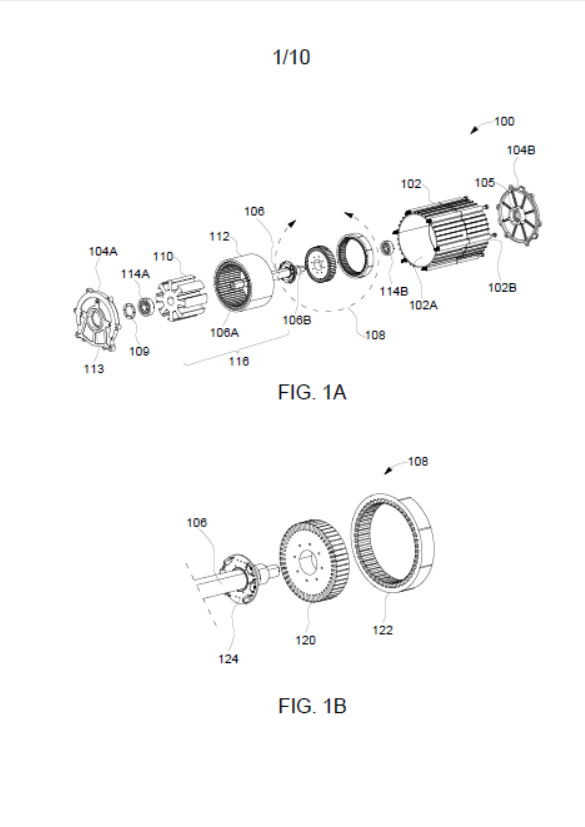 Vimag’s “Virtual Magnet” motor tries to bypass this headache by throwing physical magnets out of the window. Instead of embedding permanent magnets in the rotor, the patented motor uses a rotating transformer to transfer electrical power contactlessly to copper field windings on the rotor. A three-phase rectifier mounted on the shaft converts the alternating current received from the rotating transformer into direct current, which energizes the rotor field windings and creates the magnetic field required to operate the motor.
The “software-defined” part should be understood as the control of this electrical excitation rather than software creating magnetism by itself. Under the granted claims, the rotating transformer is controlled through a three-phase full-bridge inverter using pulse-width modulation, or PWM. By controlling the current supplied to the rotating-transformer stator, the control system can regulate the direct current delivered to the main rotor field windings and therefore adjust the strength of the rotor’s magnetic field. The claims also cover fixed-frequency operation independent of rotor speed and control of the magnetizing current within a suitable voltage range to prevent saturation of the transformer core.
In simple terms, the software and control electronics decide how the inverter should switch and how much excitation current should be supplied. The power electronics, rotating transformer, rectifier and copper rotor windings then physically generate the magnetic field. No rare-earth permanent magnets—and no brushes or slip rings—are required.
2. An Established Concept
While the name "Virtual Magnet" sounds like something straight out of a sci-fi movie, the actual technology is a classic concept in electrical engineering. In textbooks, this is known as an Electrically Excited Synchronous Motor (EESM).
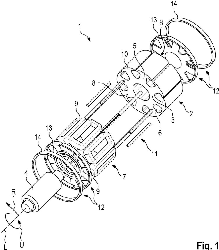
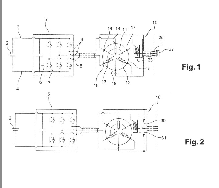
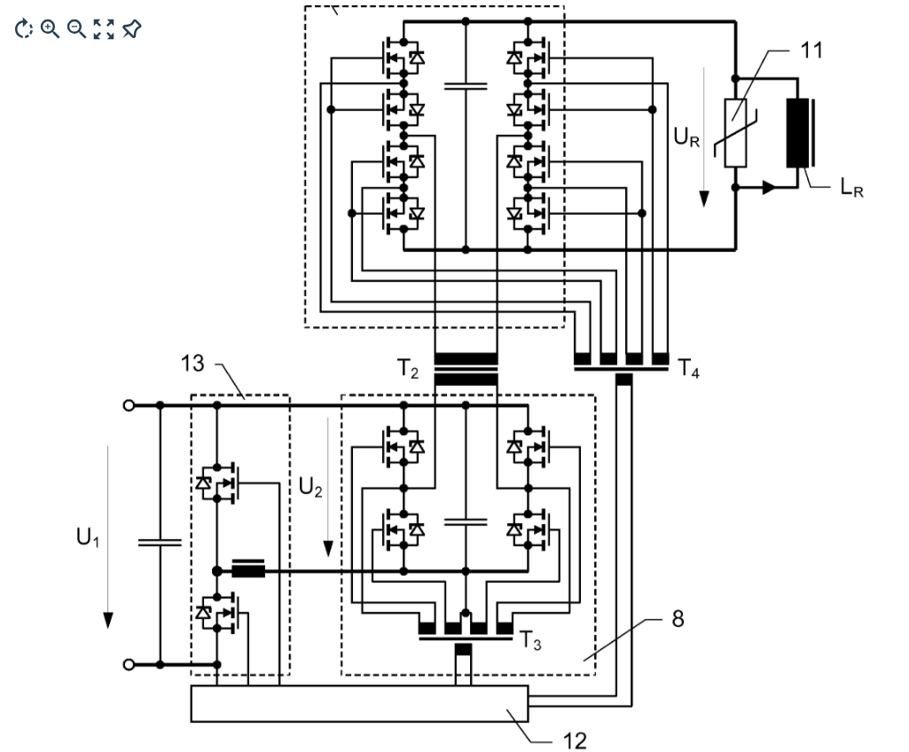
The global automotive industry hasn't been sitting around waiting for someone to invent this:
- Automotive giants are already doing this: Major carmakers like Renault and BMW have actually been mass-producing magnet-free, electrically excited motors for over a decade. Renault’s relevant patent portfolio includes EP2303628A2 relating to an electric traction system employing a separately excited synchronous motor, and FR3059487A1 relating to a wound-rotor synchronous electric machine. BMW’s portfolio includes EP2524423A1, covering control of a separately excited rotor winding through an inverter, rotary transformer and rectifier; DE102018213567B3, concerning a rotor for a separately excited inner-rotor synchronous machine; and DE102018128521A1, concerning the supporting structure of a wound rotor in a separately excited synchronous traction machine. These patent families show that electrically excited synchronous motors and related rotor-excitation technologies were established areas of automotive research and commercial development well before the subject patent’s 2022 filing.
- Decades of old patents: The specific idea of using a wireless, contactless "rotating transformer" to send power to a spinning rotor without physical contact is a well-travelled path. In fact, very similar patents detailing these exact magnet-free principles were published in 1980, 1991, and 2012.
Calling it a "Virtual Magnet" is great marketing, but the physics behind it has been standard curriculum for a long time.
Claim-chart comparison with the prior-art references
US 4,238,719 (1980) is the closest reference to the claimed rotating-transformer excitation architecture, while WO 2010/003474 A1 (2010) is the closest reference to contactless rotor-field supply and electronic current control. The comparison below focuses on the substance of the claims rather than the product name used in marketing.
| Feature in Patent No. 590023 | Subject patent claims | US 4,238,719 (1980) | WO 2010/003474 A1 (2010) | Comparison |
| Wound-field synchronous machine | Claim 1 recites a main rotor with DC field windings and a main stator with AC poly-phase distributed windings. | Claims 1 and 14 disclose a variable-speed brushless polyphase synchronous motor with a rotor wound-field winding. | Claim 1 discloses a separately excited synchronous machine with rotor excitation coils; claim 9 further refers to a stator winding and rotor coils. | The basic magnet-free, wound-field synchronous-machine concept was already known. |
| Contactless rotating-transformer excitation | Claim 1 places a rotating transformer coaxially on the machine shaft, with an RT stator and an RT rotor. | Claims 1 and 14 disclose a rotatable-transformer stator and a rotatable secondary mounted on the rotor for brushless field excitation. | Claim 1 supplies rotor excitation coils through an inductive rotary transformer having a stationary primary and a rotor-connected secondary. | Both references disclose the core idea of transferring excitation power to the rotor without brushes or slip rings. |
| Polyphase transformer windings and matched poles | Claim 1 requires AC poly-phase distributed windings on both the RT rotor and RT stator, with the same predefined number of poles. | Claim 1 expressly uses polyphase primary and secondary windings and requires the secondary to have the same number of poles as the transformer stator. | The claims identify primary and secondary windings of an inductive rotary transformer, but do not expressly require matching polyphase pole counts. | This feature is substantially disclosed by US 4,238,719 and is more specific than the express wording of WO 2010/003474 A1. |
| Rectification of transformer output into DC rotor-field current | Claim 1 requires a shaft-mounted three-phase rectifier that converts RT-rotor AC into DC supplied to the main-rotor field windings; claim 4 specifies a polyphase bridge diode rectifier. | Claims 1 and 14 disclose a rotating rectifier electrically connected to the rotating transformer secondary to produce DC for the wound field. | Claims 3 and 4 disclose an active or passive rectifier, including an AC/DC converter, between the rotary-transformer secondary and the rotor coils. | The AC-to-DC rotor-excitation path is present in both references. The exact three-phase, shaft-mounted packaging is narrower claim language. |
| Excitation behaviour over changing rotor speed | Claims 2, 3 and 6 recite low magnetizing susceptance, a low frequency-to-speed factor, fixed-frequency RT-stator operation independent of rotor speed, and low output-frequency variation relative to main-rotor speed. | Claim 1 selects transformer electrical characteristics so secondary current remains substantially independent of transformer slip over a variable-speed range; the specification also discusses coaxial arrangements transferring power independently of speed. | The primary is stationary and electronically supplied, but the claims do not expressly recite the same low-kf, fixed-frequency or low-output-frequency-variation limitations. | US 4,238,719 is particularly close to the speed-insensitive excitation objective, although the parameters are expressed differently. |
| Control of rotor-field current | Claims 5 and 8 link RT-stator current to DC field-winding current and control magnetizing current within a voltage range to avoid core saturation. | The excitation circuit derives voltage and current from the AC source and armature-converter current so the transformer-secondary current remains controlled over speed. | Claims 5-7 and 11 disclose sensing and controlling rotor-coil current, including rotor-side control components and regulation to a target value. | Electronic regulation of rotor excitation was known; the claimed saturation-control relationship and particular current dependency may be narrower implementation details. |
| Inverter and PWM control | Claim 9 controls the rotating transformer through a three-phase full-bridge inverter using PWM. | Claim 15 identifies an inverter as the armature converter, but the claims do not expressly require PWM control of the rotating transformer. | Method claim 12 expressly identifies pulse-width modulation or pulse-code modulation as a control technique for the primary-side or secondary-side voltage. | PWM-based control was expressly disclosed before the filing date, although the subject claim specifies a three-phase full-bridge implementation. |
| Housing, shaft support, endcaps and bearings | Claim 1 additionally recites a housing with two openings, a two-ended shaft, first and second endcaps, an aperture supporting an external radial load, and a groove supporting shaft rotation; claim 7 adds two ball bearings. | The reference concerns the excitation system and motor architecture, but does not claim the same detailed endcap, aperture, groove and bearing arrangement. | The reference focuses on the electrical machine and control system and does not claim the same detailed housing and shaft-support arrangement. | These mechanical packaging details are among the clearest express distinctions over the two selected references. |
What the chart shows: the broad architecture of a wound-field synchronous motor using a contactless rotating transformer and a rotating rectifier was disclosed well before this patent. The apparent claim-level distinctions lie primarily in the particular combination and packaging: the coaxial arrangement, matched polyphase transformer windings and pole counts, the specified shaft-mounted rectifier, selected frequency-to-speed and saturation-control parameters, the three-phase full-bridge PWM implementation, and the detailed endcap and shaft-support structure.
3. How Patent office’s actually evaluate
A lot of the online comments praise this patent as ultimate proof of a completely brand-new, "indigenous" invention. But it's important to understand how patent office’s actually evaluate applications.
- The patent office doesn't evaluate patriotism: Patent examiners do not look at where a company is based, how much funding they have, or how patriotic the technology is. They only look at three strict rules: Is it new? Is it useful? And is it non-obvious?
- Reading between the lines of Claim 1: If you look at Vimag's actual patent claims, you will see they list very basic things like a housing, a shaft, endcaps, and ball bearings. To a layperson, it looks like they patented the motor itself. In reality, these are just standard descriptions to set the physical scene.
- What actually got patented: Vimag successfully argued that their specific mechanical layout and software control algorithms were slightly different from what was already out there. It’s a respectable, incremental design update—not the invention of a brand-new class of motor.
4. The Engineering Trade-offs: Why It Takes Time
If magnet-free motors are a known concept, why hasn't everyone switched over yet? In engineering, there is no such thing as a free lunch—every design choice has a catch:
- The Electronics Penalty: Physical magnets give you a magnetic field for "free" because they are naturally magnetic. If you remove them, you have to actively create and control that field yourself. This means you need a second high-frequency inverter, extra computer chips, and highly complex real-time software. You are essentially trading a rare-earth supply chain risk for semiconductor complexity.
- Heat and Efficiency: Running electrical currents through spinning parts generates a lot of heat. Cooling a spinning rotor is a massive engineering headache compared to cooling stationary parts. Plus, using extra battery power to generate that magnetic field can slightly reduce the vehicle’s driving range.
- The Reliability Challenge: This is the biggest hurdle. Inside a car, these electrical parts have to spin at 12,000+ RPM and survive extreme temperatures (-40°C to 150°C) and brutal road vibrations for 15 years. Big carmakers spend years running reliability tests because they cannot afford to have a motor fail on the highway.
Conclusion: A Step Forward, But Not a Revolution
Securing a patent in a mature, highly developed field is an awesome milestone for a startup like Vimag Labs, and their engineering team should be proud of it.
But let's keep our expectations grounded in reality. Vimag hasn't rewritten the laws of physics or made the rest of the automotive world obsolete. They have engineered a clever, specific variation of a classic textbook motor. The real test of this technology won't happen in a patent registry—it will happen when they try to mass-produce it to survive the realities of the open road.
All patent details, history, and technical insights in this post were gathered entirely from public domain sources and information openly available on the internet. This analysis is shared purely for educational and informational purposes. The author assumes no legal liability or responsibility for the completeness or accuracy of this data, and is not liable for any actions taken as a result of reading this post.
Source :
https://x.com/itswpceo/status/2076989232279671221?s=48